
Micro-turbines--some obstacles
APPLICATIONS
As an easy example future miniature drones must be supplied by miniature energy sources. The best adapted seem to be micro-turbines. However, designing of turbines measuring a few cubic centimetres is a bit chancy. Researchers are looking into flow modification, the design of new geometries, micro-manufacturing and thermal studies.
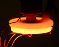 This combustion chamber only measures 20 mm in diameter and is 2.7 mm thick. Supplied by a hydrogen-air mixture, it produces a power of up to 1200 W. | Imagine drones the size of a bird, capable of flying for hours, of filming scenes and transmitting information. Many engineers are bent on designing such miniature drones, for civilian and military applications. One of the many difficulties is supplying energy to the engines, which must be both powerful and also extremely light. Batteries are too heavy and have too little independence for these micro-drones with wingspans of 15 centimetres and similar length, weighing around a hundred grams. As far as fuel cells are concerned, these do no yet exist in the range of power under research. That leaves gas turbines remain, which could provide ten times more energy than a battery with the same mass. | ||||||||||||||
A turbine transforms energy from fuel into rotational motion, either to directly supply a propeller, or to produce electricity. "Our goal is to make a micro-gas-turbine, for future micro-drones", says Joël Guidez. These micro-turbines will supply the electric motor driving the drone wings, as well as the electrical equipment, such as transducers, and even a small camera.
However, to miniaturize a turbine, it is not enough to reduce the dimensions of each component. The flows do not occur in the same way at very small scales, for example in the combustion chambers of these micro-turbines, which only measure a few hundred cubic millimetres. The flows are much less turbulent, and gases thus mix with greater difficulty. This is not desirable for a combustion chamber, where the fuel must mix with air! It is thus necessary to create structures that favour the mixture of the gases within the combustion chamber. "We design circulation areas leading hot gases toward cool gases", explains Joël Guidez. This allows the combustion to be maintained, otherwise it would be extinguished. 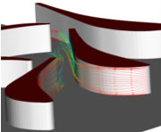 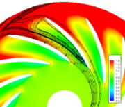 The elsA aerodynamic simulation code allows the characteristics to be optimized by revealing details of the flows between the vanes.
Meanwhile, these microscopic structures can not be too complex, or it may not be possible to manufacture them. The first chamber constructed had a quite simple geometry: It was a cylinder with a 20 millimetre diameter, 2.7 mm tall, having a tube in its centre off which the gas bounces. It is thus sent around the periphery of the chamber, where it mixes with the gases present. This chamber serves above all to test the manufacturing and measuring methods of ONERA's laboratory. The manufacture of a second, more complex and better performing chamber is underway.
To speak of small volume combustion chambers is to speak of great thermal losses. Indeed, small objects have a greater surface in relation to their volume compared to large objects, which generates more thermal losses. This is both an advantage and a disadvantage. On one hand, it prevents the walls from overheating and melting, but on the other, it may extinguish the combustion if too significant. It is thus necessary to design chambers for which the losses are just at the right level. 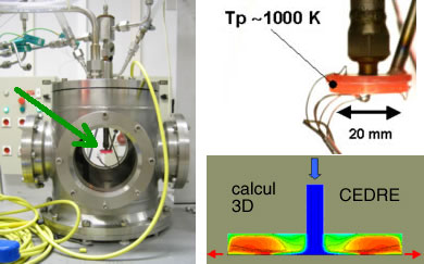 The micro-combustion-chamber and its experimental enclosure. The aerothermal simulation code Cedre allows the 3D combustion to be reproduced and to better understand the phenomena in play.
Current experiments are being carried out using hydrogen as fuel for several reasons. Since it is very light, it diffuses easily. Additionally, its chemical reaction time (the necessary time for the combustion chemical reaction to take place) is 50 microseconds, ten times shorter than that of the hydrocarbons that are usually used. Also, in a micro-combustion-chamber, the time it takes the gases to cross the combustion chamber is very brief. The more the dimensions of the chamber are reduced, the more this time is reduced. However, it must remain as five times greater than the chemical reaction time, without which combustion would be poor. On the other hand, a hydrocarbon is easier to store than hydrogen. Near future studies shall therefore be directed towards the hydrocarbon combustion stability within these very small chambers.
Which materials will be used to make these micro-turbines? The Massachusetts Institute of Technology (MIT) is endeavouring to manufacture a turbine entirely from silicon, in order to benefit from the silicon etching technologies of micro-electronics to create channels which will allow the gases to mix. ONERA prefers to manufacture micro-turbines made up of several materials. 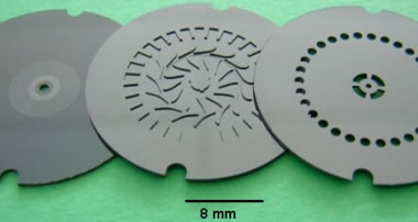 Micro-turbine rotating parts etched on silicon (SilMach).
Finally, let us not forget the rest of the gas turbine, specifically the rotating parts. The turbine vanes can be made to spin at a very great speed, up to a million revolutions per minute. The manufacture of 8mm turbine vanes can prove to be complex. Silicon etching may be a solution, unless micro-machining techniques are favoured. "This manufacture will require all sorts of specific technologies", says Joël Guidez. But the crucial question is that of the bearings and stops, which hold the turbine shaft. In the usual turbines, ball bearings serve this purpose. Here, hydrodynamic bearings would be used: the gas flows sustain the rotating parts without these touching the fixed parts.
Micro-drones are not the only potential applications of micro-turbines, which combine a high rated power and a very small size. The power supply for portable devices could also benefit from this, for example, to equip the future infantryman, transporting increasingly more electronic equipment. Nevertheless, the extremely hot gases must be evacuated.
TECHHNOLOGY
Mesoscale and Microscale Combustion / Reaction systemMotivation
Recently, there are the increasing demands on the developments of microdevices such as microsatellites, microaerial vehicles, micro reactors, and micro power generators. This project is first motivated by the development of small power generators with internal combustion and reaction for the replacement of traditional batteries. Small power generator has many advantages over batteries in that it has high energy density, it is light weight and portable, environmentally superior and inexpensive. Another example of microscale combustion /reaction system is micro fuel converter which has much higher conversion efficiency and can be used in poisonous gas disposal. Moreover, micro-chemical propulsion system developed for small spacecrafts can be used for primary thrust, orbit insertion, trajectory-control, and attitude control.
Mesoscale Flame Dynamics
In mesoscale combustion (length scale ~ quenching diameter), the increase of larger surface to volume ratio dramatically increases the wall heat loss and leads to flame extinction. On the other hand, the reduction of thermal inertia at small scale significantly reduces the response time of the wall and leads to strong wall flame coupling and extended burning limits. This flame-wall coupling can dramatically change the nature of flame propagation and yield different flame regimes. The flame bifurcation and the transition of flame regimes are dramatically affected by the channel width and flow velocity. In fact, all practical combustors have variable channel width in the flow direction. As a result, the simultaneous changes of channel width and flow rate will significantly modify the heat loss and flame-wall coupling. Therefore, it is of great interest to understand how the variation of channel width will affect the flame propagation and flame transition.
Heat recirculation mechanism (Fig. 4): Part of the heat loss from the flame to the wall can be pumped back to the preheat zone through wall heat conduction to preheat the premixture. As the scale goes down, this thermal feedback effect becomes significant and the flammability limit can be widely extended. New flame stabilization mechanism and instability phenomena can exist as well due to this flame-wall interaction.
Fig. 5 shows the experimental setup to study the flame dynamics in a mesoscale channel. Due to the strong thermal coupling between the flame and the wall, different flame dynamics and flame regimes have been observed. Fig. 6 shows the spinning flame was observed inside a mesoscale diverging quartz tube for both methane and propane at equivalence ratio ranged from lean to rich. The spinning frequency ranges from 10 HZ to 70 HZ, highly depending on the equivalence ratio. The spinning flame is a result of wall-flame thermal coupling effect.Slow flames and fast flames coexist in a mesoscale straight quartz tube. A pulsating flame is also observed (Fig. 7). Both theory and experimental result show that there exist new bifurcations and new flame regimes in mesoscale combustion. The flammability limit can be extended due to the heat recirculation effect.
Development of Micro ThrusterBased on the understanding of flame dynamics in mesoscale combustion, a preliminary version of micro thruster is developed and the schematic of design is shown in Fig. 10. Both the liquid fuel and oxidizer are issued into the main combustor through the two outer shells to minimize heat loss and maximize the heat recirculation effect. The liquid fuel is heated up by the wall and vaporized before goes through the porous quartz. A pressurized millimeter scale catalytic tube is injected into the main combustor to supply constant radical pool to stabilize the combustion. The exit of the catalytic tube is chocked to generate high speed jet to enhance the mixing.
 | |||||||||||||||


Hiç yorum yok:
Yorum Gönder